Solder Modeling


Solder is an extremely complex material whose deformation includes a combination of elastic, plastic, creep and viscoelastic modes. For instance, see Rafanelli (1992) for plastic, Tribula and Morris (1991), Mei et al. (1991), Guo et al. (1992), Hare and Stang (1995) for creep and Tien et al. (1991) for viscoelastic behavior. The as-cast joint microstructure is unstable, and shows recrystallization (Mei et al., 1991) and coarsening (Hacke et al., 1997, 1998; Vianco et al., 1999) under typical joint operating conditions. Results of Igoshev and Kleiman (2000) for silver-tin solder also indicate that it may be essential to incorporate the effects of microcracks and micropores formed during creep, to properly model solder constitutive behavior. Bulk behavior may not adequately represent the behavior of thin joints (Bonda and Noyan, 1996) and bonded joints may be subjected to both shear and normal stresses during nominal shear cycling, involving different modes of crack propagation (Yamada, 1992).


The total incremental strain in solder can be divided into elastic (e), plastic (p), anelastic (a), creep (c) parts and the thermal (T) part due to the coefficient of thermal expansion,


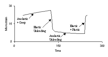
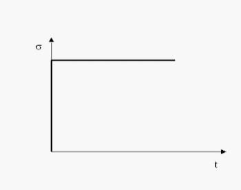
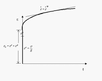
Tien et al. (1991) have indicated the contributions of various components of deformation schematically for stress‑controlled loading for a test cycle. An instantaneous step drop in the load to zero load causes instantaneous elastic strain recovery, followed by time-dependent recovery due to anelastic strains during hold at zero stress. During the next step up to the maximum load, instantaneous  elastic deformations occur, along with plastic yield. During hold at maximum load, creep and anelastic deformations are manifested.


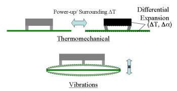
Under field conditions, joints are subjected primarily to two load regimes. Under slow thermomechanical cycling, strains are imposed due to thermal mismatch between the board and the component, the local thermal mismatch between solder and pads. The most significant mode of deformation in this case is creep. Under vibration loading, the behavior is elastic or elastoplastic, and strains are imposed on the joints due to board deformations relative to the component, which is stiffer. Combined loading conditions, with vibrations superposed on temperature cycles are also present.

Testing usually involves acceleration in terms of larger temperature and the corresponding strain amplitudes, as well as faster thermal cycling as compared to field thermomechanical loading, to conserve time. For vibratory loads, equipment that allows for substantially higher frequencies which are within the range of the natural frequency of a joint, unlike field loads which only excite vibrations in boards, may be used to direct more energy onto the joints for faster failure.

Thus, the constitutive model used should be able be applicable under a wide range of loading conditions and temperatures, if test results are to be translated into meaningful field predictions.


Elastic Deformations

Considerable variation exists in published values of the elastic modulus of solder, ranging from 14.8 GPa to 43.4 GPa (Knecht and Fox, 1991) at room temperature. The variation is caused due to the strong effects of creep and anelastic strains, with a loading rate of at least 80MPa/s required for accurate determination of the elastic modulus at room temperature (Hare and Stang, 1995). A comprehensive set of values has been provided by Pan (1991).

Measurement problems also arise due to the compliance of the test equipment (Solomon, 1986; Wilcox et al., 1990; Wang et al., 2001). Solder shows continuous yield and elastic modulus is measured at the initial portion of the stress-strain curve, where errors may arise due to any initial rocking at initiation of test . Typically, unless the corrections required for creep and machine compliance effects are overestimated, measured values are expected to be smaller than the true value.

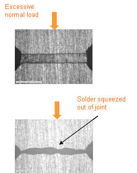
Visual monitoring such as Moiré interferometry (Guo and Woychik, 1992), or Digital Image Correlation (Desai et al 2001) shown here, which was conducted for the testing of Wang et al (2001) can help reveal the realized joint strain and aid in proper setup, such as avoiding excessive normal loads, or to detect initial rocking of sample. 

Accurate measurement of elastic parameters is important as subsequently computed parameters such as for plasticity are based on the measured elastic parameters. If the plasticity model is sufficiently complex, two different values of the elastic modulus may be assumed for a test, and two corresponding sets of plasticity parameters are obtained, each set providing a reasonable back prediction to the test.

Finite Element computations for independent problems may not provide clear enough results to determine the validity of parameters. FE results are complex enough that gross errors in commercial software may go undetected (Anderson et al, 2000). Even the small size of electronics structures may introduce errors in FE simulations conducted using commercial code (Dube and Sahay, 1996). Several issues related to the basic model and formulation itself may go undetected due to the complexity of such simulations.

The complexity of solder behavior has led to several simplifications, which typically ignore one or more deformation modes. Under such simulations, even basic parameters such as the elastic modulus must be interpreted with extreme caution as they may not correspond to the ratio of the stress to the instantaneously reversible elastic strain. Different simplifications may compute and use different values of the elastic modulus from the same test data based on the simplified interpretation.


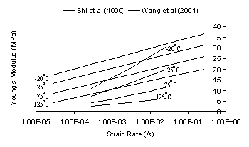
Some simplified schemes for solder use a strain rate dependent elastoplastic formulation to approximate creep behavior. In this case, material parameters are treated as strain rate dependent and the elastic parameters are obtained from the initial curve of the stress strain curve at a given temperature and strain rate, rather than as the ratio of the stress to the reversible elastic strain.  Thus, they are not the true elastic modulus. Experimental data for the apparent rate-dependence of elastic parameters along with the temperature dependence has been provided by Shi et al. (1999) and Wang et al. (2001). The values, for uniaxial and shear strains respectively are not directly comparable, without further investigation into dependence on the full strain rate tensor, as well as the effects of specific deformation mode rates such as elastic, plastic or creep. 


Apparently reasonable results were obtained in prior work based on such simplifications as the incremental elastoplastic equation used in such simulations was


which, as shown here, provides a history-dependent stress-strain relationship for elastic deformations. The generalized equation developed here, that provides the correct relationship, shows that such simplified modeling schemes to be of extremely limited utility for solder.


Rate Dependent Elastic Behavior

Click on slide buttons to navigate slideshow


Extremely reasonable predictions and extrapolations of elastic constants and the coefficient of thermal expansion are obtained in terms of two temperature-independent empirical factors as well as certain basic physical parameters, which for solder are estimated as weighted averages of its constituents, lead and tin. Details are under the solder  thermomechanical analysis.


Plastic Deformation  

Solder shows substantial creep under typical operating conditions and at slow strain rates the total irreversible strain is some combination of plastic yield and creep depending on the temperature. Dynamic testing methods to suppress creep are essential to obtain only the instantaneous, rate-independent plastic deformation stress-strain curve (Rafanelli, 1992).


The von Mises function is typically sufficient for metals. However to simulate continuous yield demonstrated by solder, elastoplastic deformation has been described using the Ramberg-Osgood model (Rafanelli, 1992, Dasgupta et al., 1992) as well as the HiSS yield function (e.g. Chia, 1994; Basaran, 1994; Dishongh, 1997; Wang et al., 2001; Desai and Whitenack, 2001; and Li, 2003).


Researchers for the HiSS function and elsewhere, e.g.  Shi et al. (1999) have also employed a simplified elastoplastic scheme, where all irreversible strain is treated as plastic and creep is sought to be approximated in terms of rate-dependent elastic and plasticity parameters.


The elastoplastic formulation used in prior work is not complete, resulting in predictions inconsistent with the fundamental generalized formulation (Dube, 2004). The complete rate-dependent elastoplastic formulation for solder is not a simplification but rather quite complex and unwieldy, apart from being potentially inaccurate because of the discontinuity in stress related to the generalized elastic incremental equation.


The rate-dependent formulation can be derived in a manner identical to that for temperature dependent materials, using the elastic incremental equation, the consistency condition and the normality rule. The complexity is introduced as the elastic incremental equation and the consistency condition now include additional terms for strain rate dependence as

and an additional term is required for the consistency condition as well,


Such a scheme would also require additional iterations in Finite Element simulations as strain rate is an internally computed parameter, as well as experimentation to develop relationships between material parameters and the full strain rate tensor and to distinguish the effects of the elastic, plastic and total strain rates. For instance, shear strain rate dependent parameters of Wang et al. (2001) may not be directly comparable to the uniaxial strain rate dependent parameters of Shi et al. (1999). Development of the complete incremental elastoplastic matrix for the strain rate dependent case is not pursued further.


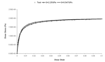
The generalized elastoplastic scheme shows that the simplified rate-dependent elastoplastic formulation is not a good approximation for solder. However, for the constant shear strain-rate isothermal tests of Wang et al. (2001), the, data does allow for elastoplastic modeling for back prediction of individual tests. Based on the data, examples are provided for the significant issues with HiSS. Prior parameters (Chia, 1994) are shown to require correction, and additionally, the significance of the improved parameter determination scheme is presented. Finally, the data is modeled with the new yield function. Details are presented in the application of the simplified elastoplastic scheme to solder.


The thermomechanical model is used to provide the instantaneous plastic behavior at the higher test temperatures by assuming the highest strain-rate test at the lowest available temperature to be elastoplastic. This allows for separate modeling of elastic, plastic and creep strains, which is an improvement over the Perzyna simulation.


Anelastic Deformations
 

Anelastic strains are time-dependent, reversible strains arising potentially due to the interaction of the tin and lead phases in solder (Tien et al., 1991). These strains can suppress damage accumulation due to creep strains depending on the loading, requiring a sufficient hold time so as to obviate their effect. Anelastic deformations in general may be due to effects such as bowing of dislocations, and may be a substantial portion of the primary creep deformations (Gittus, 1975).


Creep Effects  
   

Due to its low melting point of 183oC, solder shows substantial creep deformation, the effects of which are manifested in several ways including creep, stress-reduction at hold, and substantial dependence of stress-strain curves on strain rate and temperature.


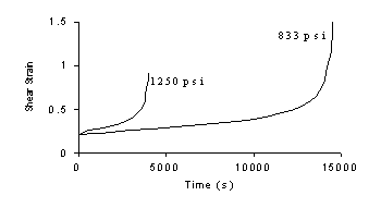
If the stress is kept constant, the strain continues to increase due to creep, as  seen from the data of Mei et al. (1991)  at 65oC.

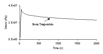
Stress reduction at constant strain hold is observed, based on the data present by Hare and Stang (1995).

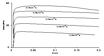
Shi et al (1999) have presented data for tests conducted at various strain rates. At lower strain rates, for a given total strain, creep strains have greater time to manifest and reduce the elastic portion of the strain, thereby reducing the stress.


For Coble creep, a = 3, n = 1, and the activation energy is that for grain boundary diffusion. At higher temperatures, Nabarro-Herring creep occurs, with a = 2. At high stresses and intermediate temperatures, dislocation glide involving climb of edge dislocations, with a stress exponent between 3 and 6 is obtained, with the energy of activation being that for vacancies to travel to climb sites. Contrary to the expectation of lack of superplasticity for as-cast joints, Mei et al. (1991) showed that liquid nitrogen quenched joints showed a stress exponent of between 2 and 3.

For the Weertman equation, Dasgupta et al. (1992) provide values of 0.5 – 0.7 and 0.08 – 0.2 for nc, for grain boundary creep and matrix creep respectively, with corresponding values of Q being 0.5 eV and 0.84 eV respectively. Climb-controlled creep has an nc of 0.14 – 0.2, while the value for superplasticity is 0.5. Yu and Shiratori (1997) have provided temperature dependent values for the stress exponent.

   
Perzyna Viscoplastic Modeling  

The Perzyna model


where


has been used to model solder in several studies, e.g. Chia (1994), Desai et al. (1997), and Wang et al. (2001). Chia (1994) has provided solder parameters for the Perzyna formulation. However, as shown in Dube (2004), the parameter determination procedure of Chia (1994) requires significant correction and parameters obtained via the two procedures differ by several orders of magnitude. Furthermore, the parameters of Wang et al (2001) are shown to require correction in order to allow for Perzyna modeling.

Additionally, at low temperatures, as predicted, the Perzyna simulation could be problematic if both plastic and creep strains are present. The Perzyna formulation cannot simultaneously model instantaneous plastic strains and creep strains. If the fluidity parameter, G,  tends to infinity, material response is elastoplastic corresponding to F = 0 at finite strain rates while if the fluidity factor is zero, the behavior is elastic. For finite, nonzero values of the fluidity parameter, all irreversible strain is viscoplastic and thus rate‑dependent.

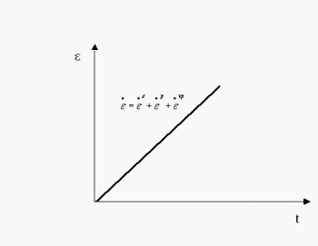
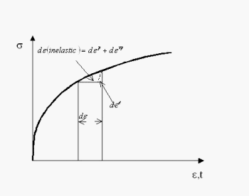
For solder, typical nominal strain rates in accelerated thermomechanical tests may be of the order of 10-2/s – 10-5/s. Under these conditions plastic strains are virtually instantaneous and thus, rate-independent.  Rate-dependence of behavior is introduced by creep strains. The relative contribution of plastic and creep deformation depends on the temperature and the strain rate. At –45oC, plastic slip may dominate at higher strain rates while at 125oC, creep dominates. Plastic strains along with multiple creep modes may contribute significantly at intermediate temperatures (Darveaux and Banerji, 1992; Stephens and Frear, 1999). Thus, the appropriate division of strains is

where the elastic and plastic strains are the reversible and irreversible instantaneous components of the total strain, while the viscoplastic strain is the time-dependent irreversible part. Viscoelastic or anelastic strains are assumed to be insignificant.


For instance, consider material response to a stress‑step loading. For fluidity parameters computed from the strain‑response to such loading, only the creep portion of strains is included in computation of viscoplastic strains.


However, if a constant strain‑rate test is used, both plastic and creep strains are included in the computation of the viscoplastic strain increments. Thus, fluidity parameters computed based on constant strain‑rate tests may be overly large even though the rate‑dependent creep effects are small at low temperatures. In the extreme case of no creep, the viscoplastic strain component from stress‑step tests is zero, while the viscoplastic strain component from a constant strain‑rate test which includes the plastic strain can be used to determine Perzyna parameters using the procedure of Desai (2001).


Reasonable creep results for solder are obtained based on the preliminary creep equation in the thermomechanical model, with three temperature-independent parameters simulating the behavior for the complete range of temperature and strain rates available from the constant strain-rate isothermal data of  Wang et al. (2001). The model also provides for separate modeling of plastic and creep strains.


Degradation Modeling

Several approaches, from the purely empirical to those based on micromechanics, with a corresponding range of simplifications, advantages and limitations have been provided in literature.

 Damage accumulation in solder in the field is typically under thermomechanical cyclic loading and is due to creep‑fatigue interactions. Comparison across fatigue studies is complicated due to the varying failure criteria used. From a functionality viewpoint, failure occurs when the solder joint does not provide the requisite connection between the component and the board. However, this is not a logical choice for fundamental stress‑strain relationships. In general, at small crack lengths, the change in resistance is small, while dramatic increases in resistance may be obtained as the joint approaches final separation (Wilcox et al., 1990).

Wild (1975) indicated that a 10% drop in resistance was obtained subsequent to the first appearance of a crack, while Solomon (1986) showed that a 0.03 mW change in resistance corresponded to a load drop of 50% to 90%.  Frear et al. (1995) have used resistance spikes of 500 W, with a duration of less than 1ms as the criterion corresponding to complete separation, which avoids contamination of results due to pressure from the leads of the joint. A substantial factor of safety may be required in applications, given the scatter in fatigue data.

Alternative criteria include a drop in load to a certain fraction of the original load. Solomon (1989) showed that the fatigue exponent for the Coffin-Manson relationship depended on the fraction selected for defining failure, especially for shear loading, while Wilcox et al. (1990) showed that results of fatigue life under this criterion are sensitive to the compliance of the test equipment. Additional criteria include initiation of a decrement in the ratio of the maximum to the minimum stress in uniaxial loading (Cutiongco et al., 1990), and the critical state of microstructure beyond which further cycling deteriorates the resistance of the material (Zubelewicz et al., 1989).

 Initial attempts to describe the behavior of solder under cyclic loads were in terms of the traditional parameters of stress and strain amplitudes, for the Coffin-Manson line, combined at times with the Basquin high-cycle fatigue law as


Solomon (1986) indicated that use of plastic strain control instead of total strain control provided a value of 0.52 for the Coffin‑Manson exponent for solder, in line with typical metal values of 0.5 – 0.6. The high homologous temperature of solder under typical operating conditions with the resultant dominance of creep indicates that additional parameters such as waveform, ramp rates, hold times could be of crucial importance. Semi-empirical modifications have been provided, such as those by Coffin (1973),


where De is the applied strain range, Nf is the number of cycles to failure, n is the frequency of loading, and the other material parameters are assumed to be temperature dependent, and by Engelmaier (1984)

with


where gf = 0.65 for 40/60 and 37/63 lead-tin solder, is the mean cycle temperature in oC, and tD is the high-cycle dwell time in minutes.

 Barker et al. (1990) added the effect of elastic strains under high-cycle fatigue using Miner’s rule for combined thermomechanical and vibratory loading, while Oyan et al. (1991) have applied the Halford-Manson strain-range partitioning scheme to account for damage due to creep and plastic strains. Creep-strain based damage models have been proposed by Knecht and Fox (1991) and Syed et al. (1998).

Vaynman et al. (1998) showed that energy based criteria may be more appropriate for solder that plastic strain based criteria, as joints which showed lower plastic strains but higher dissipated work relative to other joints were found to fail earlier. Corresponding to strain-range partitioning, Dasgupta et al. (1992) proposed an energy-partitioning scheme, wherein the damage due to the elastic strain energy stored and the inelastic work dissipated per cycle is superposed to predict solder fatigue. Lee et al. (2000) report an energy density based model developed by Akay, and an energy density based fatigue model developed by Gustafsson based on the findings of Darveaux. Zubelewicz et al. (1989) have developed a model based on micromechanical considerations.

Continuum Damage and its Extensions

Ju et al. (1996) have compared the fracture mechanics approach to that of continuum damage, and have stated that fracture mechanics requires assumptions regarding the initial crack and the path of crack growth, along with a fine mesh around the crack-tip as well as adaptive meshing, and modeling of crack failure. Qian et al. (1999) have provided a continuum damage model for solder. Ju et al. (1996) and Zhang et al. (2000) pointed to the lack of a comprehensive continuum damage theory as a drawback for the latter approach.

The classical damage theory of (Kachanov, 1958; 1986) assumes material to be composed of an intact phase and a void like phase of maximum feasible degradation that cannot carry any stress. The Disturbed State Concept (DSC) developed by Desai (2001) assumes that the material in the state of maximum feasible degradation, which is confined by the intact material, may still carry some load. Several researchers, such as Chia (1994), Basaran (1994), Dishongh (1997), Wang et al. (2001), Desai and Whitenack (2001) and Li (2003) have used DSC for modeling solder degradation. However, the issues with work balance and unloading discussed here indicate it may be better to incorporate damage within the plastic yield function, such as Gurson (1977).

An alternative approach for ductile materials that combines plasticity with the observations of local damage due to the substantial void nucleation and growth has been suggested by Gurson (1977). Needleman and Tvergaard (1984) have extended the method to void coalescence. The plasticity function in the Gurson model is given by

where f is the void fraction, se is the von Mises equivalent stress and sM is the yield stress of the matrix (Planicka et al., 2001). Void evolution is in terms of void nucleation and void growth, as

with appropriate models for each, depending on whether or not a critical void fraction has been reached. Matrix strains and continuum variables are related through the equality of plastic work,